Friday, April 17, 2015

Ferrari 308 GTS Steering Rack Rebuild -- the EASY way

Those of you who follow my blog know that I'm not exactly a "checkbook mechanic." I try to as much as possible myself and have not really farmed out any of the work so far. Once you get past the fact that Ferrari parts are outrageously expensive and that access to stuff is sometimes almost impossible, you realize that the 308 is just another car and it really is possible to do most of the work yourself.

When I decided the steering rack needed rebuilding, I did some reading online to see what was involved. The main thing is that darned passenger's side bushing which is somewhat hard to find. There are also a bunch of seals and shims that are also not exactly easy to find. Then there's the special pin wrenches required for disassembly. I did some mental math and estimate that it would have cost close to $200 in parts and tools. Posts on Fchat kept referring to the user JH355 who apparently is quite the expert on these old Cam Gears (and later TRW) steering racks. As it turns out, JH355 is local to me so I decided to just take the path of least resistance and write a check to get this done. He did a great job and as an added bonus, he turned it around in 24 hours!


Rebuilt rack looking good with new boots and new outer tie rod ends. The inner ends are metal and adjustable so they were just tightened up. My rack was completely dry inside with just trace amounts of lubrication. JH355 uses grease which is less prone to liquefying and leaking out. There was a little wear to the center part of the rack and he adjusted it with the correct amount of play at the center which means it's a little tighter at the ends. Since the rack near the center most of the time, this is the best way to set it up.


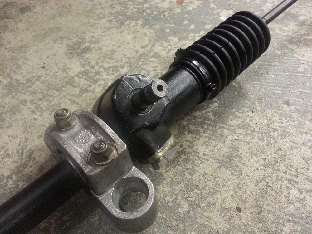
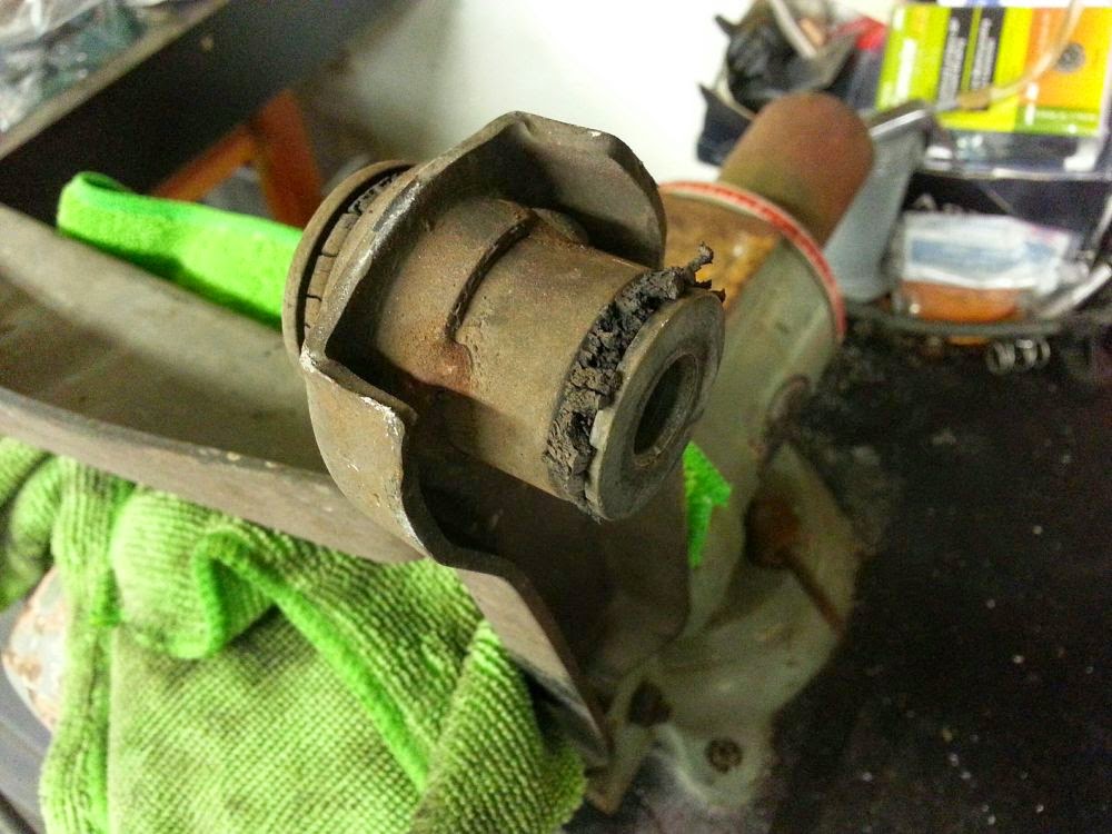
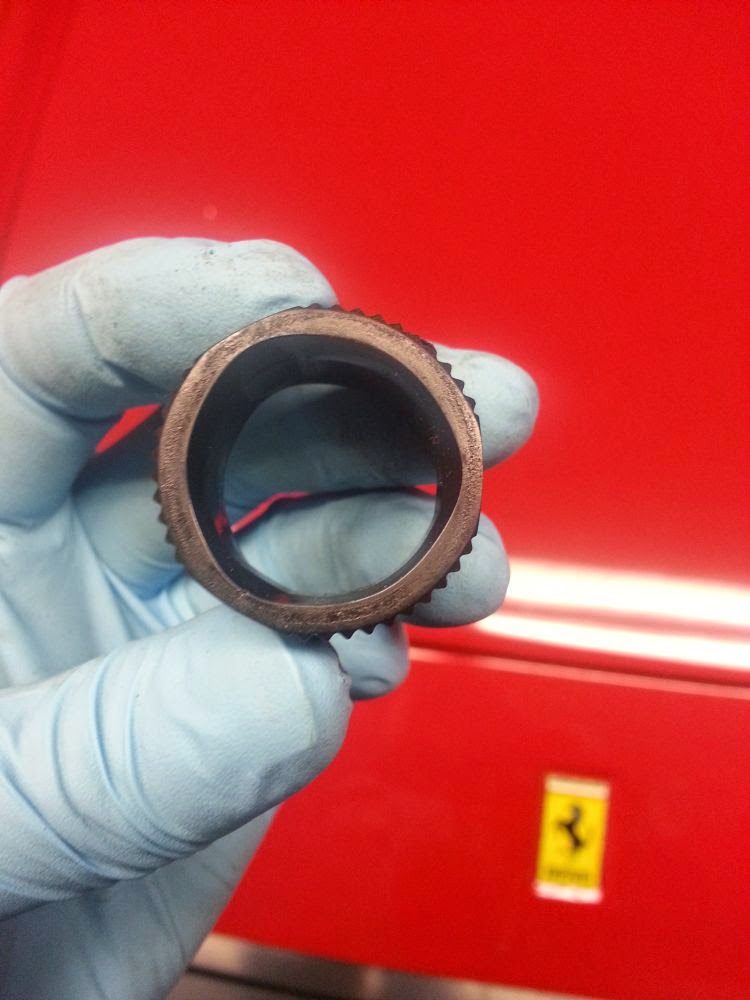
Overall, the rack was in pretty good condition. JH355 said it was one of the better ones that he's seen. I suspect that the rack was probably replaced at some point in the past, but I have no way to confirm that. Below is the infamous passenger's side bushing. Most of the time, it's completely destroyed. Mine was intact but was worn to allow about 1-2mm of play. The replacement bushing is delrin and machined with a spiral groove to allow lubricant to travel from one side of the bushing to the other. The original bushing is triangular shaped to allow this.


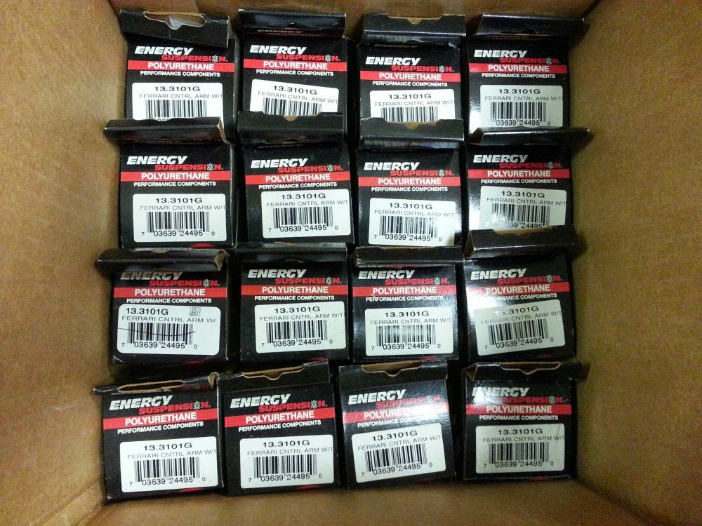
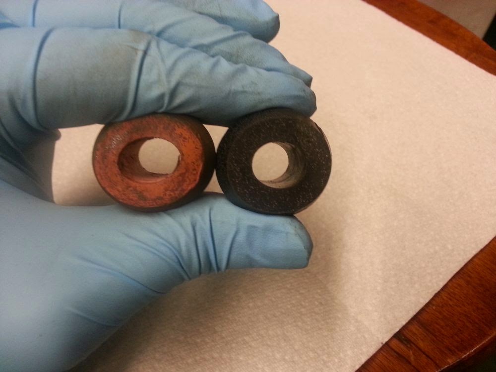
I also got some urethane rack mount bushings from JH355 to replace the original rubber ones. Even though the original bushings looked ok, they were quite soft. It's hard to tell in this photo but it shows my non-scientific method of demonstrating the relative hardness of the bushings. I'm putting about the same amount of force on both bushings and you can see how much the old ones deform. I've read about people machining new bushings out of delrin, which is what I was going to do. However, JH355 convinced me that it was better to the urethane bushings on a street car since delrin is a little too hard for this application.


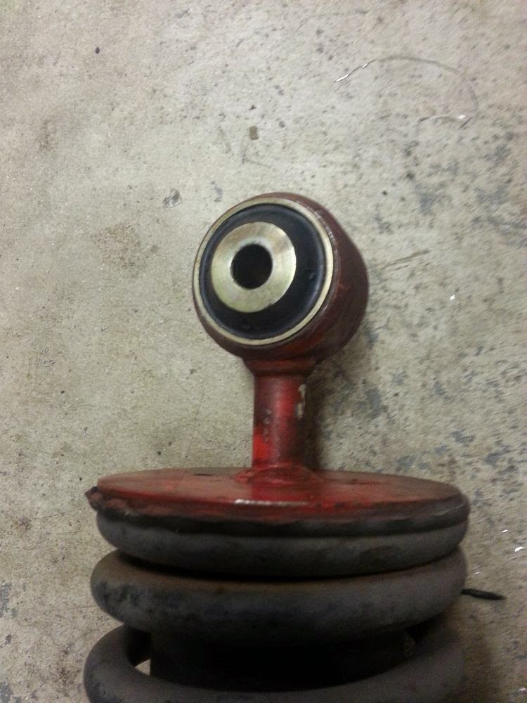
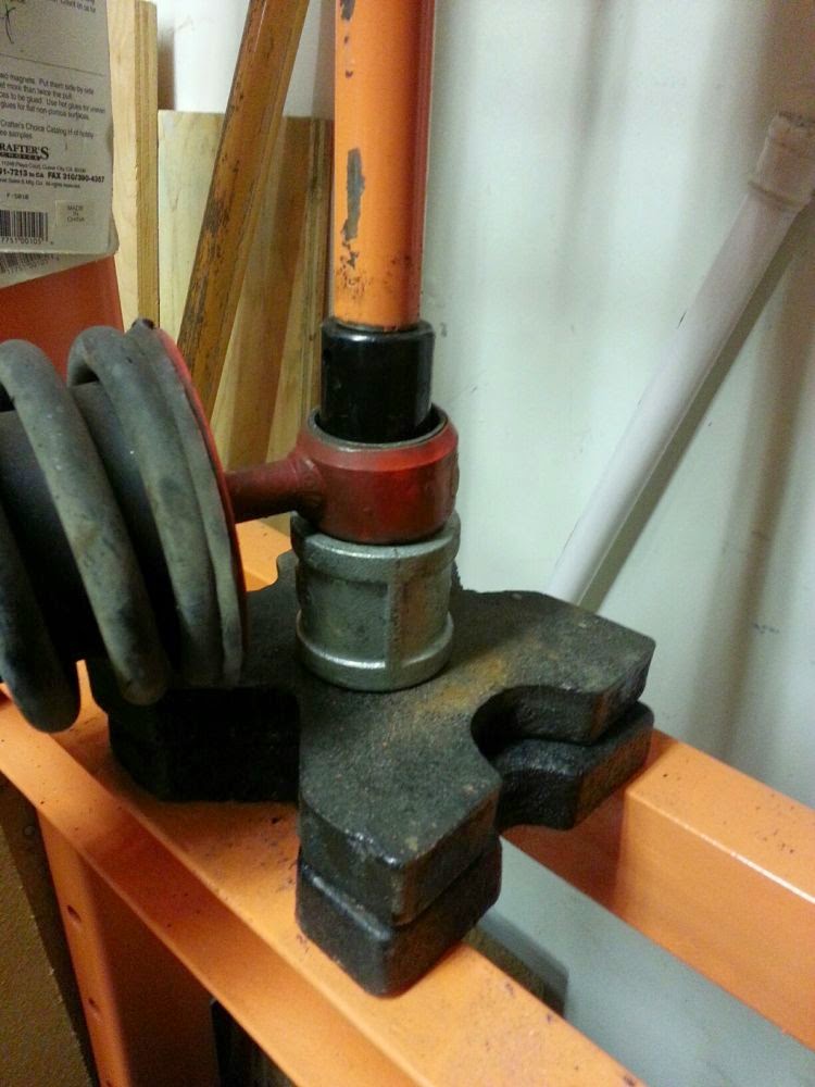
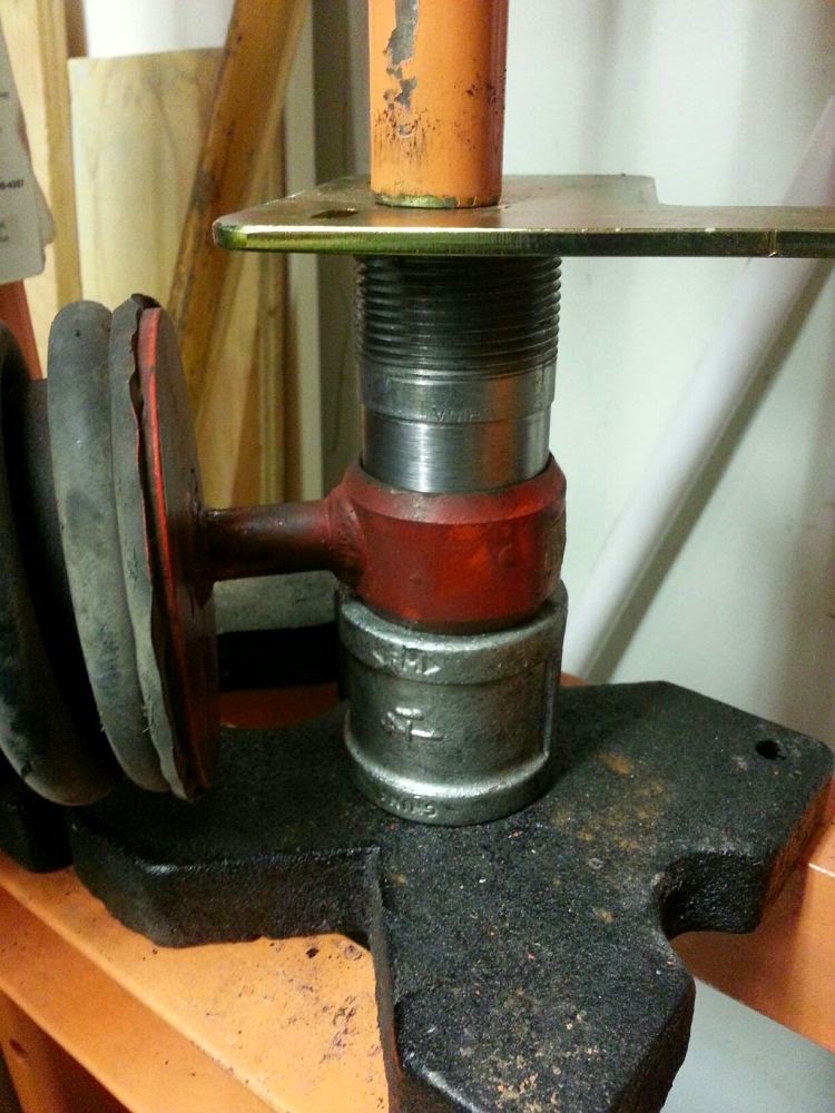
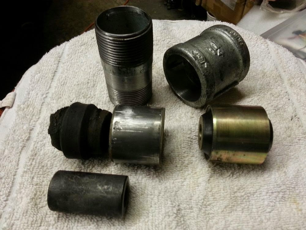
Now I just need to put it all back together. Last night I pressed out the other A-arm bushings and I just need to clean up the A-arms and apply the same anti-rust treatment as the other side. I also need to replace the shock bushings and I'll be ready to re-assemble. JH355 reminded me that the steering will be much more precise so be careful driving for the first time on new bushings.

Wednesday, April 8, 2015

More disassembly and some reassembly

Up to this point, I had only pulled apart the driver's side suspension. I spent some time and disassembled the passenger's side as well. I also decided to pull the steering rack. After all, I had everything apart already so there's no sense in not giving the rack some attention. Even though the mounting bushings looked ok and not deformed, the rubber was really soft and could stand to be replaced.


The rack itself seems to be in pretty good shape. The inner tie rod ends are fairly tight and the passenger's side bushing seemed to be intact. There was a bit of slop in the bushing end so the rack needs to be rebuilt.


I took a few minutes to press in the new shock eye bushings. Easy!


Saturday, March 7, 2015

Pressing out shock eye bushings

Initially, I was going to use the "press out the rubber then cut out the bushing shell" method. Before that though, I thought I'd have a go at pressing out the entire thing. I didn't want to risk cutting into the shock eye so this was worth a shot.

Pressing out the shock eye bushings turned out to be a fairly simple task, once you have the right tools. Isn't that always the case though? The right tools makes the hard jobs easy while having the wrong tools makes easy jobs impossible. For this job, I used a hydraulic press (12 ton cheapo from Harbor Freight < $100 on sale), a lathe, a 1 1/4" pipe coupler and a 1 1/4" pipe nipple. The 1 1/4" pipe fittings are almost the exact size needed to press out the bushing.

I started by turning the pipe coupler on the lathe. My goal was to turn the ID of the coupler to just smaller than the OD of the bushing shell. This will allow the old bushing to fall into the coupler as it's getting pressed out. Turns out that just removing the internal threads was enough of an ID reduction. Since I don't have a long boring bar, I did one side then had to flip over the coupler to cut the ID on the other side. After turning the coupler, I chucked up the 1 1/4" pipe nipple and cut the OD so it was just slightly smaller than the OD of the bushing shell. The end of the nipple comes to a knife edge so I faced it a little to get a flat surface to press against the bushing shell. I'm no machinist, but I'm starting to get pretty good at using the four-jaw chuck!


After turning, I set up the shock on the press. The shock eye sits on the pipe coupler below you press from above. I started by pressing out the bolt sleeve, then the rubber itself using sockets.


Then I set up the press using the pipe nipple pressing on the bushing shell. It takes some force to get it moving, but the 12 ton press did the job for me. There's a pop at the beginning just as the bushing shell starts to move and the rest is easy. You need to be careful at this step. The bushing shell is not very thick and lining up the pipe fitting to the shell is critical. I did both bushings on the shock this way. When I do the other shock, I think I'll try pressing out the entire bushing at once without pressing out the guts first.


Friday, March 6, 2015

Need to replace shock eye bushings too

Another thing I need to replace is the shock eye bushings. have a close look at the photos. See how the bushing is permanently deformed so the bolt hole is no longer in the center of the shock eye? I'll order up some new ones from Superformance to replace these. While I'm waiting for the parts to arrive, I guess I'll try and figure out how to remove the old bushings. I've read that these are nearly impossible to press out and a better way to go is to cut/press/burn out the center, then carefully cutting out the bushing shell. I guess I'll give this method a try.


Thursday, March 5, 2015

Left front suspension teardown

I've begun the front suspension teardown process. Like all projects, teardown is always fast but buildup can be horribly slow which is what will probably happen here. I started with the left front and disassembly was pretty straightforward. I started by removing the brake caliper and rotor. The rotor was stuck onto the hub, but it came off with some gentle persuasion with a soft blow hammer. Then I separated the ball joints and tie rod with a pickle fork. I have all new components so I wasn't worried about tearing boots with the fork. Once the steering knuckle was removed, it was pretty simple to unbolt the upper and lower A-arms.

Here's another fine example of special action required for the tight space. The end of the hard brake line is hard to reach and I had to cut off my 11mm flare wrench to have enough room to actually turn the flare nut.


The original rubber A-arm bushings looked sad. The exposed outer parts were all cracked and falling apart. I'm going to be using the 13.3101G polyurethane bushings from Energy Suspensions and following the procedures from Birdman's post on Fchat . The OEM bushings are bonded to a steel shell and the shell is spot welded into the A-arm hole. Many people in the 308 community are using this alternate method which involves just replacing the guts of the bearing while leaving the shell in place. This is what I will be doing as well.


I started by cutting off the end of the bushing using a reciprocating saw, being careful to not cut into anything important. To press out the old rubber bushings, I planned on using my cheapo HF 12 ton press. That plan got changed when I realized the A-arm won't fit in the press so I dropped to the next idea which involved sockets, a C-clamp and a propane torch. Some people burn out the old rubber but I just used the torch to heat the bushing shell. This broke the bond enough for the makeshift press to force out the rubber.


Here's a shot of the old bushing next to the new bushing. The new one does come with a metal sleeve, but the guts pull out pretty easily. The polyurethane part is in two pieces and fits inside the A-arm shell perfectly.


A lot of people decide at this point to media blast the A-arms and powder coat. I decided to not go that far. This is not a show car and maybe I would do that if I were doing a full restoration. Instead, I cleaned up the A-arms, sprayed some Permatex rust converter on the ends that were lightly rusted, then coated them with some satin clear coat. This had the added bonus of preserving the patina of these old parts. When I was cleaning, I came across "AS USA" painted on the upper A-arm. According to Fchat users, this means A-arms for the GTS USA market. No one really knows why they're marked this way from the factory, but it's a cool piece of history that would be lost forever if I blasted them.


Thursday, February 19, 2015

Steering wheel spacer -- done! (almost)

I finished the machining on the steering wheel spacer tonight. The spacer itself had been turned down to the correct diameter and I needed to make a stepped collar for the horn mount.


The inner diameter of the collar is the same size as the original steering wheel hub for the horn button and the outer diameter of the raised part of the collar is what the steering wheel center fits into. I can't remember where I got this spacer, but it certainly wasn't meant for a 308. No matter, a little lathe time and it is a perfect fit.


The stepped collar is just press fitted into the spacer. The collar OD  is very slightly bigger than the spacer ID and I don't think it's going anywhere.


I must say I'm pretty happy with the result.  The spacer looks a lot better being the same diameter as the rest of the steering column and it feels great sitting behind the wheel. That extra 1.5" brings the wheel to a perfect position and my view of the instruments is better too. The next time I'm at a store I'll pick up some matt black crinkle paint and paint it to match.